
Dunlap-Clarke Dreadnought 1000
This thing is a monster!
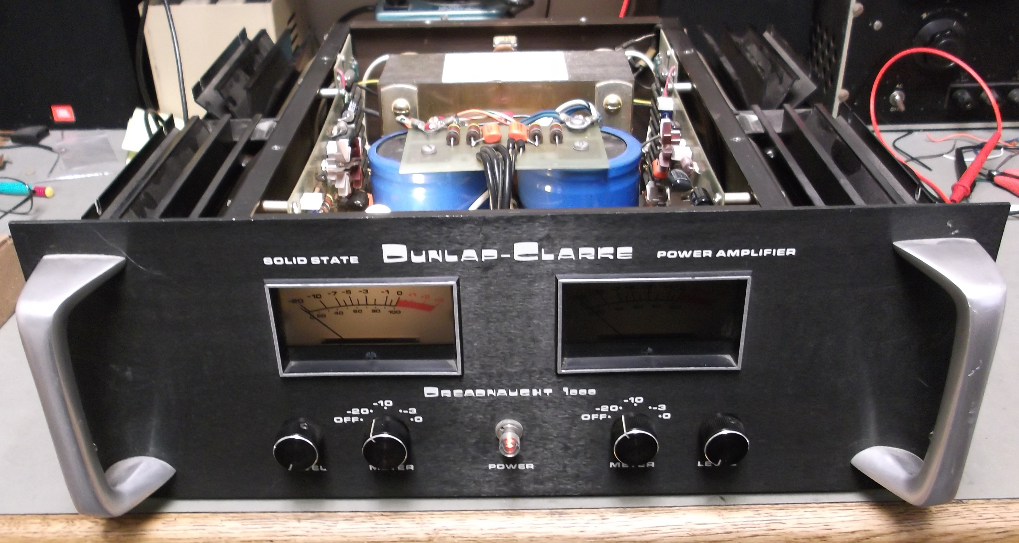
Front view of the amp. This thing wieghs around 80 lbs, and is called the 1000 because it will dump 1000 watts into 2 ohm loads. What was wrong? It blew fuses at power-up. The customer stated that a repair shop had looked at it and given up. He was, however, diligent and had accumulated a lot of information from online sources. What we did not have was a complete schematic.
The output circuit is fully complementary symmetry, and is most like a servo amplifier. The input goes to an op-amp and the feedback to that op-amp comes from the speaker output. The simplified schematic I had showed that much. The speakers are DC coupled to the output stage through fuses. Those fuses were not blown.
Of course, with blown fuses the power supply was checked first. The customer stated that the filter capacitors (huge blue cans) had leaked in the past and been replaced. He also mentioned that the output devices had been replaced. The power supply was disconnected from the amplifier circuit and brought up on a variac. No problems. So, the driver boards were removed, and each bank of output devices was checked for resistance to the positive speaker terminal. If output devices fail short, this test will show that short. In fact, the left side of the amp had shorts and an odd mix of output devices. Upon removal, some originals present were failed short. Some incorrect replacement devices were failed open. And they were mixed, which is bad practice.
According to our information, the original output devices (2N5631/2N6031) were selected by Dunlap Clarke for this amplifier based on a forward breakdown voltage of 180V, from devices specified at 160V. This is a vital clue, because those incorrect replacements were 150V devices.
At this point the repair moved into the realm of restoration. How to get the best results, in the least time for the least cost? Knowing a little about why prior replacements had failed, all new output devices were selected. ON Semiconductors’ MJ21193 and MJ21194. These are 250V, 250W, 16A devices. This is far beyond the originals and 10 of each came in just under $100. New mica insulators, replacements for 8 electrolytic capacitors and 4 39K 1W resistors on the driver boards, and a bag of 8A fuses were also ordered.
On each driver board were the 4 electrolytic capacitors, which looked OK but were old, and 2 burned 39K resistors. These were replaced as routine. Then the output devices were replaced. This is where I found that only the right side output devices had been successfully replaced in the past with some Motorola devices. All were replaced with the newly selected devices. Each new device was installed with a new mica insulator and fresh silicone grease. In fact, 16 devices are output and 4 devices of the same type are used as drivers, which are mounted separately directly to the chassis under the heat sinks.
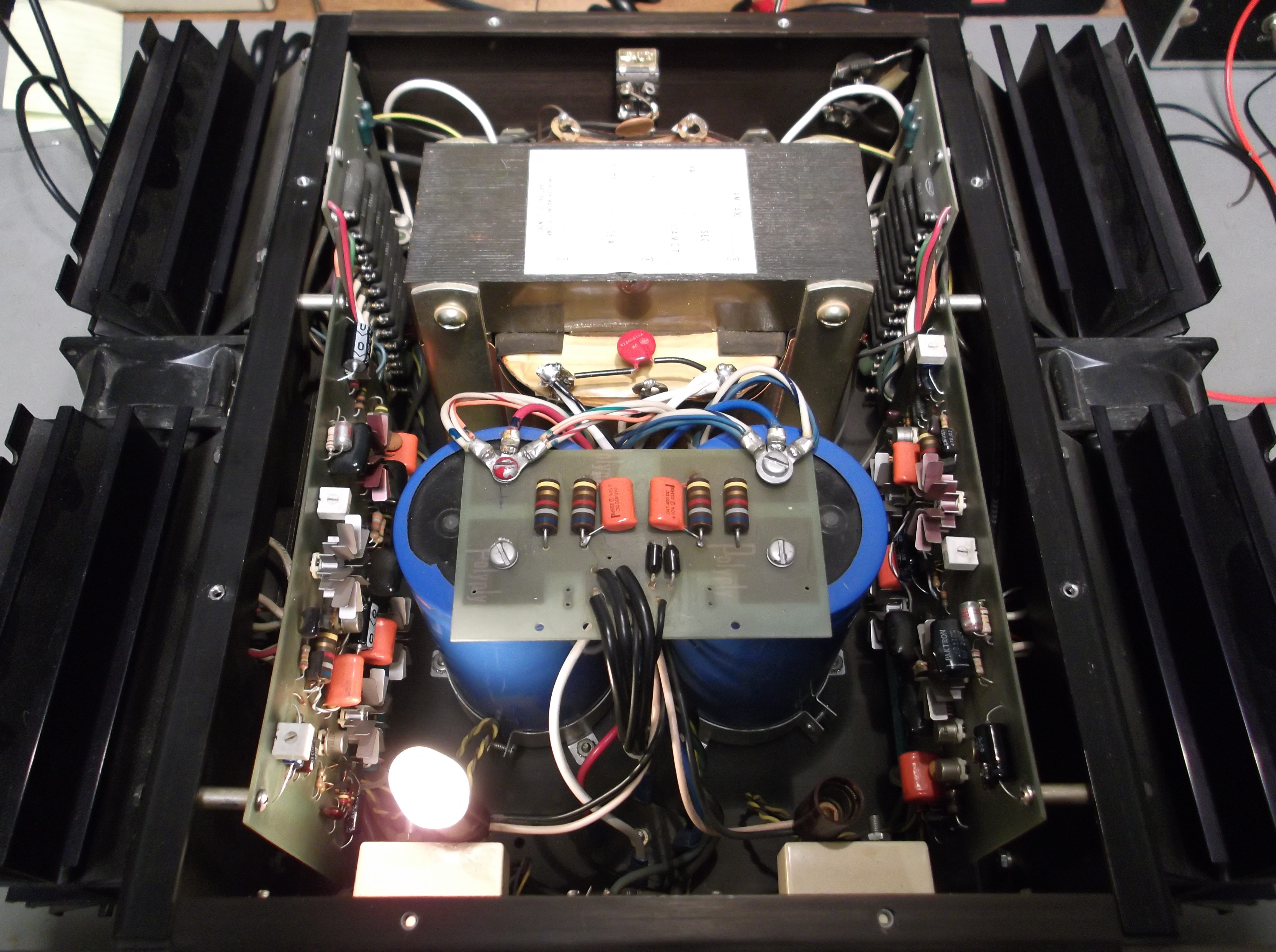
The above, a view from one side, shows everything in place.
The result? I only have an 8 ohm test load, so I tested each channel with that. Specification is 250 Watts into 8 ohms, and I measured approximately that on each channel. Nailed it! So I have to ask: How can an established professional repair shop fail at this? They’re the pros, right? This challenges that assumption!

Hello,
Any possibility to clone the dreadnought 1000?
Schematic available?
Sure, it could be cloned. I did not find a full schematic while I was looking, though. One could reverse engineer it, or redesign it.
Hi,
Can you please try to redraw the schematic?
Tq.
No, that isn’t something I can casually do for fun. I do a lot of reverse engineering in my work, making my time more valuable than ordinary technicians.
Hi,
Sorry for the disturbance. I did send you a mail requesting what is the adjustment required for the two pots at the driver board?
I got one dreadnought 1000 which is not working. I am trying to trouble shoot.
Kind regards.
Hi Raj,
When I did this repair, I was given a paper with a partial schematic on it that I returned to the customer. I can tell you these:
1- Shorted output transistors will show as shorts across the power supply and blow fuses
2- Shorted output transistors will also show as shorts from the speaker terminals to either positive or negative rails IF the output fuses aren’t blown
3- It is probably a good idea in general to replace all electrolytics in the unit, and if output transistors are shorted, replace the entire lot using new mica washers and thermal grease. Use ON Semiconductors’ MJ21193 and MJ21194. If you can’t get these, I can find another sub for you.
Of course you could send the unit to me for a complete overhaul… 🙂
Thanks for your reply,
I have managed to identify the function for the two pots. For dc offset and bias adjustment.
Will look into the MJ’s.
Regards,
Raj
Hi Bil,
I have refurbished the Dreadnought 1000 with MJ15024/15025. The amp has been working for past two months. No issues at all.
I would say the sound is incredible. Bass is something not many amps can do like it.
regards,
Raj.
Those look great too! Mouser shows the MJ15024 as obsolete, so I should mention that the currently available devices are MJ21193G and MJ21194G, for anyone listening.
Good job of troubleshooting. The devices have to have a 180 volt or greater breakdown. Manufacturers
breakdowns were variable so we selected devices using the lower breakdown power transistors for lower powered amps. Checking between the power supply and the speaker terminal is the best way to check for shorted
devices without removing individual devices. A variac with a current meter is essential. Once the supply\
holds you are all set.
The main power supply can be fused with a .25 amp fuse. The amp with function
with AC line voltage as low as 30 to 40 volts AC. Driver boards will balance up and function at this
level. The amp will run at plus and minus 25 volts DC up to plus and minus 90 volts.
Hi Ron! Looking to contact you about posting the service manuals, etc. I have some of the old devices with the red fingernail polish dot, to confirm tested, Also need advise on common mode conduction
Best Regards, Phil
Phil,
I personally wouldn’t risk using the original output devices on a unit like this. High temperature & high power operation near the device limits causes “electromigration”, which will degrade and fail the devices over time. Modern components like the MJ21193/21194 devices will outlast and outperform the originals. I know a lot of people would probably disagree, but the owner of the amplifier in this article has had it in continuous operation for over two years without any troubles, and raves about the sound.
I do not know whether Ron Dunlap will see your questions here and be able to respond. I do not myself have any literature on this amp.
-Bill
I have one of these and have it plugged into a voltage regulator set to 90 volts. Lots of power for my electrostatics and no failure of the amp in 30 years now.
What sort of “regulator” are you using?
It’s an old dial voltage regulator. It was supplied by the previous owner and looks to be about 45 years old- grey and heavy, cylindrical shape about 6 inches tall.
Fantastic amp, still working beautifully. The precious owner designed and built amps and preamps. He suggested running the Dreadnought at 90 volts just to make sure it didn’t blow any output transistors which it did occasionally. Haven’t had a problem since, even at loud volumes with electrostatic speakers.
Yes, I’m a little late to the party here 🙂
can the op amp be replace with new model to improve the sound? thx
Micromega,
Generally you would not notice any change. The entire audio chain becomes like a single unit when inverse feedback is applied. One thing that could change is noise figure, another might be improved handling of high level inputs, because many modern op-amps can swing closer to the power rails.
Hello, I have a Dulap Clarke drednought 1000 and it blows the main fuse when turned on. Replace the fuse and all is fine for a while. It has been sitting for several years now and I’d love to get it completely restored. Can this be done and if so, by who? Please help. My late father and I bought this brand new in 1975 and I love to bring it back to life! Thank you,
Russell Snyder
Replace the fuse with a SLO-BLO type of the correct Ampere rating. See if that solves it. Finding a local shop to work on these can be tricky! Getting a schematic can be a challenge, I’ve never seen a complete one If you find a local shop you trust, have them read my article and/or contact me if they need more info.
Hi Bill ,as mentioned In a October post I have a 500 I bought and its acting weird seems to there is only out put from one channel. And when you switch the RCA to other again one channel. There’s a switch which says fan but wires appear to go to inputs. It seems to me that one channel may be blown and it was wired to hide that. Or someone was trying to bridge it? Does that make any sense? As well Bill will the modern replacement transistors you mentioned in previous posts work with the 500 or would the 250v, 250w 16a be basically halved to a different transistor?
I also have a chance to buy a working 1000, what is your approximate cost on restoring a 500 and a 1000 dreadnought. I will greatly appreciate any reply, and welcome any of your thoughts. I am in Ontario Canada and the thought of finding a tech here who understands them is a bit overwhelming. Daren
Daren,
For a response, please use the contact page. The same transistors are applicable to the 500. When you email, let me know if there is audio output on one or both speaker outputs, and which one. Being in Ontario, you may need to try a local tech and put that individual in contact with me if there’s any questions.
Wow, you do great work and know your stuff, just bought dreadnought 500 and came across your post. Fantastic job
Daren,
I took a troubled amp to Soundstage in Waterloo Ontario and they fixed the problem.
Bill,
I am the owner of two BGW 1000 power amplifiers designed and built by the late Brian Gary Wachner. I believe these were one of his first amps when starting out in his garage in California. Seeing as the power specs are very similar to the Dreadnought 1000, and the handles are the same, I’m wondering if you think seeking out a Dreadnought would be a worthwhile goal.
They have intrigued me since I first read about them.
Sincerely,
Steve
Hello, I like your page. I am in the process of restoring 2 of the 500’s. One is working, but the other one is not. They appear pretty different in design, different driver boards, different components, and in the older one the power transformer is twice the size of the newer one. I made a lengthy post on this on Audiokarma. Some of the parts on the driver boards are infact military grade and the parts numbers do not cross reference to anything with an available datasheet (Texas Instruments 1854-0022/Fairchild S42728). It seems they subbed out the Texas instruments part with the Fairchild. I have used BD139G and MJE340, they both work.
The output transistors are also different parts numbers, both being Motorola, but the one that is not working has 2N3773 and 2N6609. I tested all 32 in both units and none are shorted or open. I dont remember the part number in the working one. The one I am still working on had about 6 shorted or open transistors, and several burnt resistors. Its been a nightmare getting this to work correctly. I am able to get the one board I replaced everything to pass signal. Thats about it. Will continue to work on it, and check out my post if you are interested.
https://audiokarma.org/forums/index.php?threads/dunlap-clarke-dreadnaught-500-high-dc-offset-on-one-channel.1072750/#post-17488599